MIL-PRF-2939G
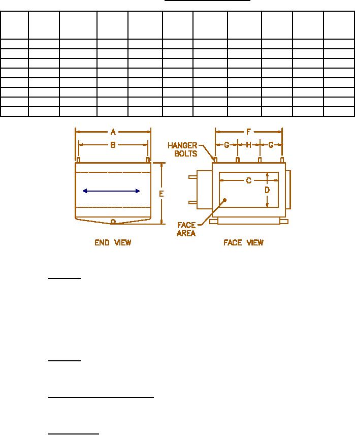
TABLE III.
Physical Dimensions.
Size
Face
Dry Wt
A
B
C
D
E
F
G
H
Area
Max
sq ft
Lbs.
In.
In.
In.
In.
In.
In.
In.
In.
61
.57
106
15
13.75
11.75
7.0
12.12
13.25
x
x
62
.90
118
15
13.75
14.00
9.25
14.38
15.50
x
x
63
1.35
169
15
13.75
21.00
9.25
14.38
22.50
x
x
64
2.00
212
15
13.75
25.00
11.5
16.62
26.50
x
x
65
3.00
280
15
13.75
31.5
13.75
18.88
33.0
16.5
x
66
5.00
404
15
13.75
39.5
18.25
23.38
41.0
13.68
13.62
67
7.50
766
17.63
16.
39.5
28.44
34.25
41.12
13.75
13.62
68
10.0
830
17.63
16.
39.5
37.44
43.25
41.12
13.75
13.62
AIR
FLOW
Class 1 Cooling Coil Interface Dimensions
3.13.10
Headers. The cooling coils shall have a supply header and a return
header. The headers shall be enclosed within the coil end cover but not in the
air stream. The headers shall be secure to the coil end cover to relieve the
header joints from stresses due to external pipe whip. The supply and return
connections to the chilled water system shall be union connections or other
connections meeting the flexibility and strength requirements of union type
connections. Connections shall be rated for a service pressure of 300 pounds
per square inch.
3.13.11
Hangers. Hangers shall have a tensile strength of a least 85,000
pounds per square inch and a yield strength of at least 35,000 pounds per
square inch.
3.13.12
Cooling element support. Intermediate supports shall be provided for
the cooling elements as necessary to prevent piping from sagging, and to
satisfy vibration and shock requirements.
3.13.13
Coil baffle. Baffles or other means shall be built into the cooling
coil to prevent condensate draining to the coil bottom from being blown into
connecting ductwork.
13
For Parts Inquires call Parts Hangar, Inc (727) 493-0744
© Copyright 2015 Integrated Publishing, Inc.
A Service Disabled Veteran Owned Small Business